I assume the M8-1 nut is to hold the lever down in place so it doesn't pop off. But I don't see how the OEM tool is held in place, it does not appear to use the threads on the stem?
Right, the OEM tool does not use the threads, it just slides over the post. It seems to be held in place by weight, and the spring tension of the tool when engaged. I think the threads are provided on the post by ZF, the transmission manufacturer, so that the vehicle OEM could attach a release cable with the nut. Honda doesn't do this, instead, they offer the release tool.
Care to share your thoughts and maybe the design you've come up with so far?
I agree with the temp concerns in the engine bay, though the use of this tool would most likely only be for a few minutes, and I was thinking of increasing some bulk in the printed part for strength and thermal mass. I agree with PETG or ABS for the final version.
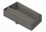
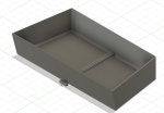
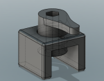
Here's the concept I've started that mimics the Honda mechanism, which consists of at least two parts - a handle for turning, and a base that slides over the transmission casting for a base. I added a hole in the base, for something like a pin to hold the handle in the released position.
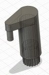
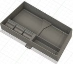
Concerned about using the printed part to turn the metal post, I did some research on similar tools, and acquired a
Lisle 20400 Shock Absorber Tool for about $15. If the oblong hole fits the park release post, I was thinking of adapting the handle in my design to have a hexagonal hole to accept the metal part, which would take most of the stress. I think a large enough handle around the hexagonal shaft could be made strong enough for the application. Then it's just a matter of devising a way to hold the handle in the released position.


 , but I imagine it will work just as well on an RL.