Honda Ridgeline Owners Club Forums banner

Head unit replacement for 2017 RTL

82K views 77 replies 34 participants last post by  Rtp6321  
First - thank you SO much for posting this. Its perfect - exactly what anybody would need to replace the head unit in their RTL/Sport regardless of replacement choice. Figuring out how to get all the steering wheel controls to work is the final piece of the puzzle for me - without that I wasn't going to do it. I also appreciate that you figured out the mic issues so I will go in knowing what is likely to be needed.

A couple of questions -

- Do you find that 3pos switch for the camera mode worth it? I was thinking of just making it fixed. I don't think people swap modes very much anyway. Not that it was much extra work to add it, just curious.
- Is there any way to zoom the rear camera like the stock unit must do? I wonder if that's a feature of head units?
- It is tempting to figure out something to do with those CAN bus lines - did you investigate that at all? Did you leave the leads accessible in case you wanted to so something with it later?

Thanks again!!
 
I just wanted to say thanks again. Just so you know somebody is getting value from your hard work (and effort to document it and share) I ordered up all the cables and connectors today based on your excellent posts. I'm still deciding what head unit/amp to select as I might wait until one of the recently announced units becomes available (and potentially drives down the price of the older models.)
 
In case anybody else is doing this, I was able to remove the pins from the Metra connector without destroying it. For the smaller pins in the middle, use a pick in the slot to push down on the little tab and pull the pin out by gently pulling on the wire. The top part allows access to the tab from the slot above the pin (shown in picture) while the lower pins have a specific guided hole below them you need to use.

To remove the larger pins in the corners, push them out of the connector using a pliers. They are spring-clipped in kinda. There must be a thin tweezers-like tool to remove them but nothing I have is quite right. But the good news is you can remove one pretty safely by just pushing it out. It is easiest after you have removed all the other pins.
 

Attachments

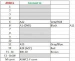
Silgen just checking, but I think your connection list for the ASWC-1 has a small error.

Pin 9 on the ASWC-1's connector is brown, not red and connects to the 3.5" data jack. I think you meant to indicate Pin 12 which is red and is the +12V power in should connect to A24 (Acc power)?

That changes the connection list to list below:
 

Attachments

I just wanted to mention to anybody doing this that if you take all the small pins out of the Maestro connector you'll have some of the wires you need to connect to the 24-pin connector (the one that connects to the video, mic, aux in, and camera controls). Those wires fit great into the Mouser connector if you snip off the very end pin part. You're left with a wire that has a little square tube on the end that can fit over the tiny pins and get easily soldered into place. I found it much, much easier to connect those wires to whatever I wanted versus trying to solder a bare stranded wire directly to the very small pins on the 24-pin JAE connector. I soldered the ground, mic and video cable directly to it and it was a major PITA. My old hands just aren't steady for what feels like doing SMT work. By using the spare unused wires from the Maestro connector it was a lot easier.

Finally, when you are done and have shrink wrapped all the individual connections, you might want to use hot glue to anchor the wires to the connector. I don't think they are under any strain, but I have no idea what might happen in the long run. Finally, I found using the Tesa cloth tape added a lot of strength to the wire bundle - much more than just regular electrical tape. YMMV.
 
A couple of additional tips.

I couldn't get the ASWC-1 to work until I grounded it to its own ground location. I had mixed its ground in with an overall grounding point for the rest of the components but it didn't power up until I moved it.

And this seems obvious, but Pin 11 of Connector A (SWC GND) really does need to be connected to a ground - it can't float. I thought perhaps it was a bug in the diagram, but no.

Also, soldering the tiny (22 gauge?) mic wires is rough. I tinned the wires ahead of time, tinned the connection pin, got out my smallest SMT tip for my soldering iron and was just barely able to get them to attach. That was the biggest pain for me. The resulting connection is then super flimsy. I covered the connected pins with hot glue to try to give them some strength and I still had one of the wires break during installation.

I cut out a little scrap piece of flat 1/8" wood about 3/4" x 2", cut a hole in it, and used that to anchor the mic to the visor using the screws that held the stock mic(s).

I decided I didn't care to adjust the sub after install - I left the AALC out. I also decided I didn't need to adjust the rear view camera. I don't tow anything so that's not a big deal to me. I went ahead and connected wires to the C connector in case I change my mind. Finally, I also didn't connect up the AUX input jack. Given that you can connect via USB and Bluetooth I can't see why I would need to use a 3.5" jack in the future?
 
silgen - any tips on getting the ASWC-1 to work with the HFL buttons? The ASWC-1 recognizes both wires (red/grey and blue/grey) as being connected (light 4 and 6 long flash) and I checked connectivity to the right pins on the connector. But I can't get it to recognize the HFL buttons. I go into manual configuration mode and it recognizes the volume cluster just fine but not the other 3 even if I attempt to assign them to other functions.

This is the last thing I want to get working - I hope it isn't a FW issue with the ASWC-1 even though I upgraded FW to the latest last weekend.
 
JoeT - if you read silgen's initial post, you'll see that the Metra 1729 wiring harness does not contain the right number of pins for a 2nd gen Ridgeline. I can 100% confirm this is true. Without those 4 missing pins you can't connect to the subwoofer or the steering wheel controls without splicing into the Honda wires. I suppose you could stop using the built-in subwoofer, but I would really miss the steering wheel controls.

Also, the USB cable silgen lists (PAC USB-TY1 Toyota/Lexus OEM USB Port Retention Cable) works to connect the Honda console USB to the radio.

I think you want Metra 40-HD11 HONDA ANTENNA ADAPTER CABLE. This cable contains the power wire that I think the Ridgeline uses. I suspect the antenna would still mostly work without being powered but I don't think you're going to be happy with this. I don't have any experience with the HD13 though.

Finally, you might want the Reverse wire connection - you have to splice into the Honda harness as silgen points out. This is required if you want the rear view camera to come on when you put the car in reverse automatically. If you don't need this, you must manually select the camera.
 
And a couple HU's actually have various modes for camera view right on the unit.
The funny thing about the Ridgeline camera is that it does some processing in the camera itself. That's why it takes 6 pins when you'd expect only 2 or 3. The other 3 are for a mode change that tells the camera what view to show (normal, wide, or hitch view), and I don't think any HU will do the exact thing the Honda wants. That said, list the ones you are looking at because I'd be interested in looking at them.
 
I finally gave up on getting the 3 'hands free telephony' buttons to work and buttoned up my dash for now. The Axxess unit detects the HFL wire is connected but won't recognize any of the button presses. I suspect this is a FW issue, so I'm going to be keeping an eye out for an update from them in the future.

I was able to stash the Axxess unit behind the hazard/airbag indicator and I'm hoping I can pop that out and pull the little box out to access its USB and LEDs in the future without having to dismantle the entire dash. We'll see.

Otherwise my project was a success. I followed silgen's plan/directions closely and it was a tremendous leg up. RZRPilot did a lot of the heavy lifting to determine what wires in the harness to use, and silgen finished it off with an approach to using the Metra harnesses to avoid splicing into any wires.

I ended up using the Kenwood DMZ7704s because it had all the features I wanted - HD Radio (being dropped from next-gen Kenwoods), CarPlay, Android Auto, large display. I used the same sub silgen did and I wedged it in behind the spot where the CD player goes (although I don't have a CD player). I left out the subwoofer level adjust, the camera switch, and the connection to the AUX 3.5" input in the center console.

CarPlay is super easy to use and a great feature. Android Auto is a PITA (cable issues, app issues, etc.) but once its working is also very cool. Now I wish I had it in my other car (Corvette) but that's way too big a project to tackle.
 
The screen is fine here in Texas sun. I wish the Ridgeline angled radio display towards the driver, but other than that I didn't notice an issue with washout. Kenwood's angle feature made a difference.

I also notice the touchscreen is much more responsive than the one in my Sienna and Corvette despite all of them being resistive screens. I wanted the capacitive screens that are being launched now but I'm OK with how it is. The new ones dropped HD Radio which I wanted.
 
After operating this for a few months I wanted to pass along a few things.

First, my Axxess unit doesn't operate when it gets hot. When my truck sits out in the Texas sun I lose the steering wheel controls repeatedly. I'm going to see if I can re-position the module to be lower down and perhaps nearer to A/C air to fix this.

Second, sometimes (rarely) my Kenwood head unit doesn't output audio at all. If I cycle the power (turn off/on the truck) it comes back. So far this has happened 3x in the last 12 months. I think it is probably a firmware/software issue with the head unit but it might be in the hardware? This is annoying but not game breaking.

Scott
 
I make car electronics for living.

Difference –Aftermarket to OEM :
OEM all electronics is designed and tested to work from -40 to +85 deg Celsius.
It is so called automotive temperature range.

Aftermarket - maybe some more serious company develop their units under automotive requirements, but generally no one know this.

Just simple example – same electrolytic capacitor but one time covering automotive
Qualification AEC-Q200 standard and same one but commercial grade – first one is around 2 times more expensive.
Oh yeah, I make commercial electronics for a living and we are always respectful of the work you and the other automotive engineers have to do to make things for cars. From specialized components (the caps mentioned are a great example) to ASIC operating modes to FW behavoir to high specialized enclosures, the automotive world certainly has its unique requirements!

I work with some suppliers who also supply automotive and how they take a commercial product (like a USB chip) and make it work in automotive is fascinating.