Honda Ridgeline Owners Club Forums banner

Head unit replacement for 2017 RTL

82K views 77 replies 34 participants last post by  Rtp6321  
#1 ·
I gave up on the (in)capabilities of the Honda head unit and decided to replace it for my 2017 RTL. One of my main goals was to have no splices to RL wiring so I could put back the stock equipment if needed. I outline the main points of my experience for those who would like to try this.

First, here are some threads that helped me.

Very detailed head unit replacement thread:
http://www.ridgelineownersclub.com/forums/161-2g-audio-bluetooth-electronics-navigation/140489-base-radio-swap-info.html
2016 Pilot info on connectors and removal/disassembly (applies to 2017 RL):
2016 Honda Pilot Service Info - Honda Pilot - Honda Pilot Forums

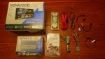
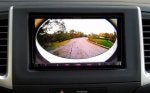
I went with a Kenwood receiver. Boot up time, quick availability of rear view camera image were the key factors in the selection. I guess you can’t go wrong with any head unit compared to the stock Honda ships with. I also installed a small Kenwood amp for the subwoofer. Existing wiring were used for speakers, steering wheel control, rear view camera, FM antenna, USB, and Bluetooth microphone. I was not able to use the Honda BT microphone – it is powered with DSP that optimizes reception for different use cases. Although I applied power and used attenuators on the output, the sound had noise and clipping. At the end, I replaced the Honda microphone with the Kenwood one, using RL wiring. I had to do one single splice on the reverse wire since that was not available in any connector that I could find.

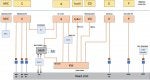
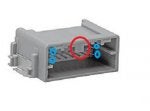
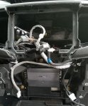
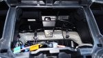
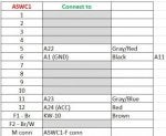
Challenging parts were populating the Metra harness with additional connector pins (RL used more pins than the Metra connector offered), wiring the amp power lines from the battery, and getting the mike to work. Android auto is very finicky with respect to USB wiring – I had to select good quality cables to get consistent results.

It took me a couple of weekends to get this done with all the trial and error testing and quite of bit of online research. Overall functionality is much better than what I had. And I had fun.
 

Attachments

#2 ·
Here is the list of parts I needed to get going:

• Kenwood DDX 9704S receiver
• Kenwood KAC-M3001 mono amp
• Metra-95-7811B Matte Black Double DIN Stereo Dash Kit
• Metra 70-1729 (Need 2 of these to populate missing pins since RL uses more pins than the Metra harness).
• Metra AX-CAM6V 12V to 6V Camera Stepdown
• Metra ASWC1 Steering Wheel Control Interface
• Metra 40-HD11 HONDA ANTENNA ADAPTER CABLE
• PAC USB-TY1 Toyota/Lexus OEM USB Port Retention Cable
• PAC USB-DMA Dash-Mount Adaptor for USB Accessories
• SPDT switch
• Connectors: MX34024UF1 / MX34016UF1 / MX34012UF1 (Original is MX34R08HF4T) - www.mouser.com
• Axxess AALC Remote RCA Level Controller
• Metra IBR-AK20 Amp install kit
 

Attachments

#64 ·
Here is the list of parts I needed to get going:

• Kenwood DDX 9704S receiver
• Kenwood KAC-M3001 mono amp
• Metra-95-7811B Matte Black Double DIN Stereo Dash Kit
• Metra 70-1729 (Need 2 of these to populate missing pins since RL uses more pins than the Metra harness).
• Metra AX-CAM6V 12V to 6V Camera Stepdown
• Metra ASWC1 Steering Wheel Control Interface
• Metra 40-HD11 HONDA ANTENNA ADAPTER CABLE
• PAC USB-TY1 Toyota/Lexus OEM USB Port Retention Cable
• PAC USB-DMA Dash-Mount Adaptor for USB Accessories
• SPDT switch
• Connectors: MX34024UF1 / MX34016UF1 / MX34012UF1 (Original is MX34R08HF4T) - www.mouser.com
• Axxess AALC Remote RCA Level Controller
• Metra IBR-AK20 Amp install kit
Thanks for posting this. When shopping around for a HEAD unit for my 2009 RL there are so many different sized screens. What is the standard size to look for that fit the dash ?
 
#3 ·

Attachments

#5 ·
The Metra harness is used for Audio connector A. Mine came with 13 pins populated. I needed 4 more to cover steering wheel controls and subwoofer. I bought a second connector to harvest pins for the additional 4. It was quite a challenge to remove the pins – at the end I had to cut through the plastic to be able to remove the pins without damage.

I got the other connectors for Audio C (MX34024UF1), CD Player (MX34016UF1), and Mic from mouser. The 8 pin Mic connector (MX34R08HF4T) is only sold in volume so I had to get a 12 pin (MX34012UF1) instead. I had to cut through a plastic guide tab and remove 4 pins to be able to use it with the RL mike connector.

Audio connector E is directly connected to 40-HD11 antenna adapter and connector F is directly connected to PAC USB-TY1 USB Cable.
ASWC1 is used for steering wheel control. It detected volume and channel controls automatically, but I had to manually add the Bluetooth hands free controls.
AX-CAM6V is used for the camera power. I used a 3 position switch to get the 3 views for the camera. The wide angle view is showing a much wider angle than the original. The stock head unit might be doing some cropping of the image.
 

Attachments

#6 ·
I was able to fit the Kenwood amp under the head unit. I wired the power line from the battery through the driver side wheel well and the grommet used for the running board wiring, under the driver side carpet. Then routed that through the fuse box area to the center console. Added a level controller for subwoofer volume control (AALC Remote RCA Level Controller).

For the mike setup, I removed the RL circuit board from the mike housing and replaced it with the Kenwood mike. Proper grounding of the shield pin is critical to reduce noise.

Reverse wire is on connector D in under dash fuse box. Pin 8 (Brown wire) is BACK LT signal.
https://drive.google.com/file/d/0B_oKpK0tjrpqeWNqd3ZlSUtKbzA/view

I mounted the Kenwood GPS under the dash. Working fine.
 

Attachments

#7 ·
Wow that is a lot more involved then it used to be. Of course it has been a few years since I installed an after market stereo in a car. Nice job.

I am glad to see that it can be done with only one splice to the factory wiring. Is there a reason that you got a new amp for the sub and are you using the stock sub still? Would you have been able to utilize the stock sub amp without cutting any wires?
 
#10 ·
First - thank you SO much for posting this. Its perfect - exactly what anybody would need to replace the head unit in their RTL/Sport regardless of replacement choice. Figuring out how to get all the steering wheel controls to work is the final piece of the puzzle for me - without that I wasn't going to do it. I also appreciate that you figured out the mic issues so I will go in knowing what is likely to be needed.

A couple of questions -

- Do you find that 3pos switch for the camera mode worth it? I was thinking of just making it fixed. I don't think people swap modes very much anyway. Not that it was much extra work to add it, just curious.
- Is there any way to zoom the rear camera like the stock unit must do? I wonder if that's a feature of head units?
- It is tempting to figure out something to do with those CAN bus lines - did you investigate that at all? Did you leave the leads accessible in case you wanted to so something with it later?

Thanks again!!
 
#11 ·
The 3 position switch is useful. I usually use the normal and top down views when parking. It is not backlit so at times you will need to search for it in the dark.

Kenwood does not have any capability to crop/pan the video coming in. Not a real problem for normal or top down views. You see blockage it in wide view though.

I could not find much on Honda canbus. Not sure specs are public.
 
#22 ·
Apologies if i'm not understanding this correctly, but are you saying that with the aftermarket head unit you can still swap between the three view modes? Can you still see the back up lines?

There was one photo that was posted of the rearview camera through the new head unit, and it looks like its looking through a tube, why is that?

Looking forward to your response.
 
#12 ·
I just wanted to say thanks again. Just so you know somebody is getting value from your hard work (and effort to document it and share) I ordered up all the cables and connectors today based on your excellent posts. I'm still deciding what head unit/amp to select as I might wait until one of the recently announced units becomes available (and potentially drives down the price of the older models.)
 
#14 ·
Great write up. The diagrams are a huge help. I didn't see any of the harness as having an rca for the back up camera. Did you have to splice into the female rca input on the kenwood? Is the anc still active with the new Mic? Was all the wiring for the Mic worth it as opposed to just plugging the kenwood Mic in and clipping it somewhere. I'm getting ready to pull the trigger on an audio upgrade and all this info is invaluable.
 
#15 ·
It might not be obvious from the connection diagram or matrix but I soldered RCA jacks to the C connector for camera video in, microphone audio in, as well as AV in. Here is a photo of that connector.

ANC is disabled once the stock head unit is removed.

I did not want to clip the mike but you certainly can. I tried to use the stock mike but the circuitry was too complex to adapt it to the Kenwood recevier. So I just used the wiring to hide the Kenwood mike.
 

Attachments

#16 · (Edited)
In case anybody else is doing this, I was able to remove the pins from the Metra connector without destroying it. For the smaller pins in the middle, use a pick in the slot to push down on the little tab and pull the pin out by gently pulling on the wire. The top part allows access to the tab from the slot above the pin (shown in picture) while the lower pins have a specific guided hole below them you need to use.

To remove the larger pins in the corners, push them out of the connector using a pliers. They are spring-clipped in kinda. There must be a thin tweezers-like tool to remove them but nothing I have is quite right. But the good news is you can remove one pretty safely by just pushing it out. It is easiest after you have removed all the other pins.
 

Attachments

#17 · (Edited)
Silgen just checking, but I think your connection list for the ASWC-1 has a small error.

Pin 9 on the ASWC-1's connector is brown, not red and connects to the 3.5" data jack. I think you meant to indicate Pin 12 which is red and is the +12V power in should connect to A24 (Acc power)?

That changes the connection list to list below:
 

Attachments

#23 ·
As long as you install a 3 position switch to provide the appropriate signals to the camera, you can swap between view modes. The back up lines are a function of the after market head unit. Since the new receiver does not know about multiple angles, it only has one set of back up lines you can program.

Honda installed an extreme wide angle camera and used SW in their stock head unit to crop the image to remove the blockage seen in the wide angle image. My after market head unit does not have crop / zoom functions. Some others may have it.

I use normal / top down views mode which minimize this blockage.
 
#24 ·
I just wanted to mention to anybody doing this that if you take all the small pins out of the Maestro connector you'll have some of the wires you need to connect to the 24-pin connector (the one that connects to the video, mic, aux in, and camera controls). Those wires fit great into the Mouser connector if you snip off the very end pin part. You're left with a wire that has a little square tube on the end that can fit over the tiny pins and get easily soldered into place. I found it much, much easier to connect those wires to whatever I wanted versus trying to solder a bare stranded wire directly to the very small pins on the 24-pin JAE connector. I soldered the ground, mic and video cable directly to it and it was a major PITA. My old hands just aren't steady for what feels like doing SMT work. By using the spare unused wires from the Maestro connector it was a lot easier.

Finally, when you are done and have shrink wrapped all the individual connections, you might want to use hot glue to anchor the wires to the connector. I don't think they are under any strain, but I have no idea what might happen in the long run. Finally, I found using the Tesa cloth tape added a lot of strength to the wire bundle - much more than just regular electrical tape. YMMV.
 
#25 ·
A couple of additional tips.

I couldn't get the ASWC-1 to work until I grounded it to its own ground location. I had mixed its ground in with an overall grounding point for the rest of the components but it didn't power up until I moved it.

And this seems obvious, but Pin 11 of Connector A (SWC GND) really does need to be connected to a ground - it can't float. I thought perhaps it was a bug in the diagram, but no.

Also, soldering the tiny (22 gauge?) mic wires is rough. I tinned the wires ahead of time, tinned the connection pin, got out my smallest SMT tip for my soldering iron and was just barely able to get them to attach. That was the biggest pain for me. The resulting connection is then super flimsy. I covered the connected pins with hot glue to try to give them some strength and I still had one of the wires break during installation.

I cut out a little scrap piece of flat 1/8" wood about 3/4" x 2", cut a hole in it, and used that to anchor the mic to the visor using the screws that held the stock mic(s).

I decided I didn't care to adjust the sub after install - I left the AALC out. I also decided I didn't need to adjust the rear view camera. I don't tow anything so that's not a big deal to me. I went ahead and connected wires to the C connector in case I change my mind. Finally, I also didn't connect up the AUX input jack. Given that you can connect via USB and Bluetooth I can't see why I would need to use a 3.5" jack in the future?
 
#26 ·
silgen - any tips on getting the ASWC-1 to work with the HFL buttons? The ASWC-1 recognizes both wires (red/grey and blue/grey) as being connected (light 4 and 6 long flash) and I checked connectivity to the right pins on the connector. But I can't get it to recognize the HFL buttons. I go into manual configuration mode and it recognizes the volume cluster just fine but not the other 3 even if I attempt to assign them to other functions.

This is the last thing I want to get working - I hope it isn't a FW issue with the ASWC-1 even though I upgraded FW to the latest last weekend.
 
#27 ·
I used the manual programming instructions (page 3) from https://metradealer.com/files/aswc/ASWC-1_INST_2001.pdf

Press and hold Vol up for 20 secs
Press and hold Vol Down until LED lights up
Press and hold Next until LED lights up
Press and hold Prev until LED lights up
Press and hold Source until LED lights up
Press Vol Up
Press Vol up
Press Vol Up
Press Vol up
Press Vol Up
Press Vol up
Press and hold Talk until LED lights up
Press and hold Hangup until LED lights up
Press and hold Pickup until LED lights up
Press and hold Vol up for 10 secs until LED goes out
 
#28 · (Edited)
Spoke to qualitymobilevideo.com about plug-in-play options for upgrading 5" to after market. I was given a list of these items....excluding the actual radio, of course. Parts given were basically for listed pilot, but the tech told me that individual vendors list that these items are for both RL and Pilot. Seems to make sense. The only issue is there is nothing available to connect up the USB in console. However, most aftermarket units have that function right on them. And a couple HU's actually have various modes for camera view right on the unit.

Please forgive my ignorance. It's been a while since I replaced a factory radio with an upgrade, and I really do not want to loose functionality.

Your thoughts??? Any experience with this reseller? The tech really seemed to know his stuff and was very confident. I'd really like to hear from the community. Thanks.

Metra 40-HD13 Honda and Acura Antenna Adapter, $14.99
Metra 40-HD13 Honda and Acura Antenna Adapter

Axxess ASWC-1 Universal Steering Wheel Control Interface for Aftermarket radio, $49.99
Axxess ASWC-1 Universal Steering Wheel Control Interface for Aftermarket radio

Axxess AX-HON24RVC-6V Honda Factory backup camera retention / addition harness, $17.99
Axxess AX-HON24RVC-6V Honda Factory backup camera retention / addition harness

Metra 70-1729 TurboWires Wiring Harness for 2008 and Newer Vehicles Honda, $4.99
Metra 70-1729 TurboWires Wiring Harness for 2008 and Newer Vehicles Honda

Metra 95-7811B Double DIN Radio Installation kit for 2016 - and Up Honda Pilot; $21.99
Metra 95-7811B Double DIN Dash kit for 2016 - and Up Honda Pilot
 
#30 ·
And a couple HU's actually have various modes for camera view right on the unit.
The funny thing about the Ridgeline camera is that it does some processing in the camera itself. That's why it takes 6 pins when you'd expect only 2 or 3. The other 3 are for a mode change that tells the camera what view to show (normal, wide, or hitch view), and I don't think any HU will do the exact thing the Honda wants. That said, list the ones you are looking at because I'd be interested in looking at them.